Overview
This project showcases everything I’ve learned while studying for the CCNA exam.
Each section outlines the steps taken and commands used to configure and verify the features and protocols listed below.
The project is extensive, so I recommend using the Table of Contents for quick navigation.
Naming Conventions
Naming Conventions
| Abbreviation | Meaning |
|---|---|
| ISP | Internet Service Provider |
| ER | Edge Router |
| CSW | Core Switch |
| DSW | Distribution Switch |
| ASW | Access Switch |
| PC | Personal Computer |
| SRV | Server |
Device Models
Device Models
| Category | Model | IOS Image | Version |
|---|---|---|---|
| Router | C2911 | C2900-UNIVERSALK9-M | 15.1(4)M5 |
| L3 Switch | C3650-24PS | CAT3K_CAA-UNIVERSALK9-M | 16.3.2 |
| L2 Switch | C2960-24TT | C2960-LANBASEK9-M | 15.0(2)SE4 |
Initial Configurations
Hostnames
Hostnames
To configure the hostname for each device I first entered Privilege EXEC mode by issuing the enable command from User EXEC mode.
From Privileged EXEC mode, I entered Global Configuration mode by issuing the configure terminal command.
Finally, from global configuration mode, all devices were configured with hostnames using the hostname x command where x is the hostname.
Here’s the output shown in the terminal when successfully configuring the hostname of ER1:
Router>en
Router#conf t
Enter configuration commands, one per line.  End with CNTL/Z.
Router(config)#hostname ER1
ER1(config)#
Enable Secrets
Enable Secrets
To protect the configurability of each device an enable secret of cisco was set using the enable secret cisco command from global configuration mode.
Here’s the output shown in the terminal when attempting to enter Privileged EXEC mode after setting the enable secret:
ER1>en
Password:
ER1#
Local User Accounts
Local User Accounts
The local user account aiken with the encrypted password of cisco was created on each device using the username aiken secret cisco command from global configuration mode.
This local user account will later be configured to authenticate remote access attempts via the VTY lines.
Here’s a partial output of the running configuration of ER1 showing the newly configured user account:
!
username aiken secret 5 $1$mERr$hx5rVt7rPNoS4wqbXKX7m0
!
Setting a Domain
Setting a Domain
The domain aiken.com was configured on each device by issuing the ip domain-name aiken.com
This will later be required to configure remote access via SSH.
I also executed the no ip domain-lookup to avoid attempts by the device to resolve typos to ip addresses.
Here’s a partial output of the running configuration of ER1 showing the newly configured settings:
!
no ip domain-lookup
ip domain-name aiken.com
!
Configuring Console Line
Configuring Console Line
To avoid having a command chopped in half in the middle of typing it, I enabled synchronous logging.
First, I went into line configuration mode by executing the line console 0 command from global configuration mode.
Then, I issued the command logging synchronous from line configuration mode.
I also set a 20-minute inactivity timer using the exec-timeout 20 command in line configuration mode.
Here’s a partial output of the running configuration of ER1 showing the Console Line configuration:
!
line con 0
 exec-timeout 20 0
 logging synchronous
!
EtherChannels
Layer-2 EtherChannel (LACP)
Layer-2 EtherChannel (LACP)
After connecting two redundant links between the Distribution Switches, I grouped them into an EtherChannel allowing them to function as a single logical link.
The layer-2 EtherChannel was configured using LACP by issuing the Channel-group 1 mode active command in interface configuration mode.
Here’s the output of the show etherchannel summary command on DSW1 confirming the EtherChannel is L2 and in use.
DSW1#show etherchannel summary
Flags:  D - down        P - in port-channel
        I - stand-alone s - suspended
        H - Hot-standby (LACP only)
        R - Layer3      S - Layer2
        U - in use      f - failed to allocate aggregator
        u - unsuitable for bundling
        w - waiting to be aggregated
        d - default port


Number of channel-groups in use: 1
Number of aggregators:           1

Group  Port-channel  Protocol    Ports
------+-------------+-----------+----------------------------------------------

1      Po1(SU)           LACP   Gig1/0/1(P) Gig1/0/2(P)
Layer-3 EtherChannel (PAgP)
Layer-3 EtherChannel (PAgP)
Like the layer-2 EtherChannel, two redundant links were connected between the Core Switches and grouped into an EtherChannel allowing them to act as a single logical link.
The layer-3 EtherChannel was configured using PAgP by issuing the Channel-group 1 mode desirable command in interface configuration mode.
Here is the output of the show etherchannel summary command on CSW1 confirming the EtherChannel is L3 and in use.
CSW1(config-if)#do sh eth sum
Flags:  D - down        P - in port-channel
        I - stand-alone s - suspended
        H - Hot-standby (LACP only)
        R - Layer3      S - Layer2
        U - in use      f - failed to allocate aggregator
        u - unsuitable for bundling
        w - waiting to be aggregated
        d - default port


Number of channel-groups in use: 1
Number of aggregators:           1

Group  Port-channel  Protocol    Ports
------+-------------+-----------+----------------------------------------------

1      Po1(RU)           PAgP   Gig1/0/1(P) Gig1/0/2(P)
L3 Routed Interfaces
L3 Routed Interfaces
To create the layer-3 EtherChannel, I enabled ip routing globally on each layer-3 Core Switch using the ip routing command in global configuration mode.
Then, to convert a standard switchport to a routed port, I issued the no switchport command on G1/0/1 and G1/0/2 in interface configuration mode.
Here’s a partial output of the show interfaces status command on CSW1 showing the newly configured routed ports:
CSW1#show interfaces status
Port      Name               Status       Vlan       Duplex  Speed Type
Po1                          connected    routed     auto    auto
Gig1/0/1                     connected    routed     auto    auto  10/100BaseTX
Gig1/0/2                     connected    routed     auto    auto  10/100BaseTX
VLANs
VLAN IDs
VLAN IDs
There are 4 VLANS configured in this network
- VLAN 10: Computers
- VLAN 20: Phones
- VLAN 30: Servers
- VLAN 99: Management
| VLAN | Name |
|---|---|
| 10 | Computers |
| 20 | Phones |
| 30 | Server |
| 99 | Management |
Each Vlan was created using the Vlan x command in global configuration mode where x is the vlan number.
I then named each VLAN using the name x command in vlan configuration mode where x is the name of the vlan.
Here’s a partial output of the show vlan command verifying the newly configured VLANs on DSW1:
DSW1(config)#do show vlan

VLAN Name                             Status    Ports
---- -------------------------------- --------- -------------------------------
10   Computers                        active
20   Phones                           active
30   Servers                          active
99   Management                       active
VTP VLAN Propagation
VTP VLAN Propagation
Once the VLANs were successfully created on DSW1 I propagated them to all other Distribution and Access Switches.
This was done by first configuring each Switch to use aiken.com as the VTP domain by issuing the VTP domain aiken.com command from global configuration mode.
Then, I configured DSW1 as a VTP server by issuing the VTP mode server command from global configuration mode.
The remaining switches were configured as VTP clients using the VTP mode client command from global configuration mode.
Here’s the output of the show VTP status command on DSW1:
DSW1#show vtp status
VTP Version capable             : 1 to 2
VTP version running             : 2
VTP Domain Name                 : aiken.com
VTP Pruning Mode                : Disabled
VTP Traps Generation            : Disabled
Device ID                       : 0001.4251.50C0
Configuration last modified by 0.0.0.0 at 3-1-93 00:21:14
Local updater ID is 0.0.0.0 (no valid interface found)

Feature VLAN :
--------------
VTP Operating Mode                : Server
Maximum VLANs supported locally   : 1005
Number of existing VLANs          : 9
Configuration Revision            : 13
Note: After the VLANs successfully propagated, all switches were placed into VTP transparent mode using the VTP mode transparent command for security.
Trunk Port Configuration
Trunk Port Configuration
All links between Distribution and Access Switches were manually configured as 802.1q trunks using the switchport mode trunk command from interface configuration mode.
Each trunk was configured to only allow the 4 specific VLANs (listed in the VLAN IDs section) using the switchport trunk allowed vlan command from interface configuration mode.
Each trunks native VLAN was then set to VLAN 1000, an unused vlan for security, using the switchport trunk native vlan command from interface configuration mode.
Here’s the output of the show interfaces trunk command on DSW1 verifying the configurations:
DSW1(config-if)#do sh int trunk
Port        Mode         Encapsulation  Status        Native vlan
Po1         on           802.1q         trunking      1000
Gig1/0/3    on           802.1q         trunking      1000
Gig1/0/4    on           802.1q         trunking      1000
Gig1/0/5    on           802.1q         trunking      1000

Port        Vlans allowed on trunk
Po1         10,20,30,99
Gig1/0/3    10,20,30,99
Gig1/0/4    10,20,30,99
Gig1/0/5    10,20,30,99

Port        Vlans allowed and active in management domain
Po1         10,20,30,99
Gig1/0/3    10,20,30,99
Gig1/0/4    10,20,30,99
Gig1/0/5    10,20,30,99

Port        Vlans in spanning tree forwarding state and not pruned
Po1         10,20,30,99
Gig1/0/3    10,20,30,99
Gig1/0/4    10,20,30,99
Gig1/0/5    10,20,30,99
Access Port Configuration
Access Port Configuration
All Access Switch switchports connected to end hosts were first configured as access ports using the switchport mode access command in interface configuration mode.
Each interface was configured to access the appropriate VLAN using the switchport access vlan x command, where x is the vlan number.
Here’s a partial output of the running configuration on ASW1 showing the access port configurations for Fa0/1 and Fa0/2:
!
interface FastEthernet0/1
 switchport access vlan 10
 switchport mode access
!
interface FastEthernet0/2
 switchport access vlan 10
 switchport mode access
!
Voice VLAN
Voice VLAN
ASW3’s Fa0/1 interface is connected to IP Phone 1, and PC3 is connected to the switchport on IP Phone 1.
To allow tagged traffic from both VLANs 10 and 20 on Fa0/1 without configuring it as a trunk port, the switchport voice vlan 20 command was executed in interface configuration mode.
Here’s Fa0/1's interface configuration as shown in the running configuration on ASW3:
interface FastEthernet0/1
 switchport access vlan 10
 switchport voice vlan 20
Additionally, here’s a partial output of the show vlan command on ASW3:
ASW3#show vlan

VLAN Name                             Status    Ports
---- -------------------------------- --------- -------------------------------
10   Computers                        active    Fa0/1
20   Phones                           active    Fa0/1
Securing Unused Switchports
Securing Unused Switchports
The remaining unused Distribution and Access Switch ports were manually configured as access ports (to disable DTP) and administratively disabled using the shutdown command for security.
Here’s the output of the show interfaces status command on ASW1:
ASW1(config-if)#do sh int st
Port      Name               Status       Vlan       Duplex  Speed Type
Fa0/1                        connected    10         auto    auto  10/100BaseTX
Fa0/2                        connected    10         auto    auto  10/100BaseTX
Fa0/3                        disabled     1          auto    auto  10/100BaseTX
Fa0/4                        disabled     1          auto    auto  10/100BaseTX
Fa0/5                        disabled     1          auto    auto  10/100BaseTX
Fa0/6                        disabled     1          auto    auto  10/100BaseTX
Fa0/7                        disabled     1          auto    auto  10/100BaseTX
Fa0/8                        disabled     1          auto    auto  10/100BaseTX
Fa0/9                        disabled     1          auto    auto  10/100BaseTX
Fa0/10                       disabled     1          auto    auto  10/100BaseTX
Fa0/11                       disabled     1          auto    auto  10/100BaseTX
Fa0/12                       disabled     1          auto    auto  10/100BaseTX
Fa0/13                       disabled     1          auto    auto  10/100BaseTX
Fa0/14                       disabled     1          auto    auto  10/100BaseTX
Fa0/15                       disabled     1          auto    auto  10/100BaseTX
Fa0/16                       disabled     1          auto    auto  10/100BaseTX
Fa0/17                       disabled     1          auto    auto  10/100BaseTX
Fa0/18                       disabled     1          auto    auto  10/100BaseTX
Fa0/19                       disabled     1          auto    auto  10/100BaseTX
Fa0/20                       disabled     1          auto    auto  10/100BaseTX
Fa0/21                       disabled     1          auto    auto  10/100BaseTX
Fa0/22                       disabled     1          auto    auto  10/100BaseTX
Fa0/23                       disabled     1          auto    auto  10/100BaseTX
Fa0/24                       disabled     1          auto    auto  10/100BaseTX
Gig0/1                       connected    trunk      auto    auto  10/100BaseTX
Gig0/2                       connected    trunk      auto    auto  10/100BaseTX
Inter-VLAN Routing with SVIs
Inter-VLAN Routing with SVIs
To route VLAN traffic, SVIs for each VLAN were created on each Distribution Switch using the interface vlan x command from global configuration mode.
For DSW1, each SVI is configured with the second usable IP address in the subnet and DSW2’s SVIs are configured with the third usable IP address.
This leaves the first usable address in the range to be used as the virtual IP when configuring HSRP groups (see the HSRPv2 section for more information).
Here’s a partial output of the show ip interface brief command on DSW1 confirming the SVI’s IP assignments:
DSW1#show ip int br
Interface              IP-Address      OK? Method Status                Protocol
Vlan1                  unassigned      YES unset  administratively down down
Vlan10                 10.0.10.2       YES manual up                    up
Vlan20                 10.0.20.2       YES manual up                    up
Vlan30                 10.0.30.2       YES manual up                    up
Vlan99                 10.0.99.2       YES manual up                    up
Rapid-PVST+
Enabling RPVST+
Enabling RPVST+
To prevent layer-2 loops in the network, Rapid PVST+ was enabled on all Distribution and Access Switches using the spanning-tree mode rapid-pvst command.
Note that STP is not operating north of the Distribution layer by design.
In the Core layer, scalability, speed, and resiliency are prioritized. Therefore layer-3 dynamic routing is employed as it scales better, re-converges faster, and doesn’t block ports like STP.
Configuring the Root Bridge
Configuring the Root Bridge
We can manipulating the root bridge election and force network traffic to take a predicable path through the network.
Also, by electing a different root bridge for each VLAN we can load-balance network traffic across different links.
However, in this project I selected DSW1 and DSW2 to be the primary and secondary root bridges for all VLANs by adjusting their STP priorities.
I made DSW1 the primary root bridge for each VLAN using the spanning-tree vlan 1-100 priority 0 command from global configuration mode.
Additionally, I made DSW2 the secondary root bridge for each VLAN using the spanning-tree vlan 1-100 priority 4096 command from global configuration mode.
Here’s the output of the show spanning-tree vlan 10 command on DSW1:
DSW1(config)#do show span vlan 10
VLAN0010
  Spanning tree enabled protocol rstp
  Root ID    Priority    10
             Address     0001.43E7.9398
             This bridge is the root
             Hello Time  2 sec  Max Age 20 sec  Forward Delay 15 sec

  Bridge ID  Priority    10  (priority 0 sys-id-ext 10)
             Address     0001.43E7.9398
             Hello Time  2 sec  Max Age 20 sec  Forward Delay 15 sec
             Aging Time  20

Interface        Role Sts Cost      Prio.Nbr Type
---------------- ---- --- --------- -------- --------------------------------
Gi1/0/1          Desg FWD 4         128.1    P2p
Gi1/0/3          Desg FWD 4         128.3    P2p
Gi1/0/2          Desg FWD 4         128.2    P2p
Gi1/0/5          Desg FWD 4         128.5    P2p
Gi1/0/4          Desg FWD 4         128.4    P2p
Po1              Desg FWD 3         128.29   Shr
Portfast & BPDU Guard
Portfast & BPDUGuard
To allow access ports to bypass the learning state and immediately transition to the forwarding state I configured Portfast.
Portfast was enabled globally on all Access Switch access ports by issuing the spanning-tree portfast default command in global configuration mode.
To protect the network from unintended topology changes, I also configured BPDUGuard. This will err-disable access ports that receive BPDUs.
BPDUGuard was enabled globally on all Portfast enabled ports by issuing the spanning-tree portfast bpduguard default command in global configuration mode.
Here we can see Portfast and BPDUGuard are enabled in the output of the show spanning-tree summary command on ASW1:
ASW1(config)#do sho span sum
Switch is in rapid-pvst mode
Root bridge for:
Extended system ID           is enabled
Portfast Default             is enabled
PortFast BPDU Guard Default  is enabled
Portfast BPDU Filter Default is disabled
Loopguard Default            is disabled
EtherChannel misconfig guard is disabled
UplinkFast                   is disabled
BackboneFast                 is disabled
Configured Pathcost method used is short

Name                   Blocking Listening Learning Forwarding STP Active
---------------------- -------- --------- -------- ---------- ----------
VLAN0001                     3         0        0          1          4
VLAN0010                     1         0        0          3          4
VLAN0020                     4         0        0          0          4
VLAN0030                     3         0        0          1          4
VLAN0099                     3         0        0          1          4

---------------------- -------- --------- -------- ---------- ----------
5 vlans                     14         0        0          6         20
Triggering BPDUGuard
Triggering BPDUGuard
To trigger BPDUGuard, I connected a new switch to the access port Fa0/4 on ASW1.
Here we can see Fa0/4 enter the err-disabled state after it receives a BPDU from the new switch:
ASW1(config)#int f0/4
ASW1(config-if)#no shut

ASW1(config-if)#
%LINK-5-CHANGED: Interface FastEthernet0/4, changed state to up

%LINEPROTO-5-UPDOWN: Line protocol on Interface FastEthernet0/4, changed state to up

ASW1(config-if)#%SPANTREE-2-BLOCK_BPDUGUARD: Received BPDU on port FastEthernet0/4 with BPDU Guard enabled. Disabling port.

%PM-4-ERR_DISABLE: bpduguard error detected on 0/4, putting 0/4 in err-disable state
Additionally, here’s a partial output of the show interface Fa0/4 command on ASW1
ASW1#show int fa0/4
FastEthernet0/4 is down, line protocol is down (err-disabled)
There are a few options to re-enable an err-disabled interface.
We can administratively down-and-up the port manually or we can configure err-disable recovery.
Unfortunately, Packet Tracer’s emulated devices and images do not support err-disable recovery (as far as I can tell) so we are left with the manual option.
IP Addressing
Addressing Overview

Point-to-Point Networks
Point-to-Point Networks
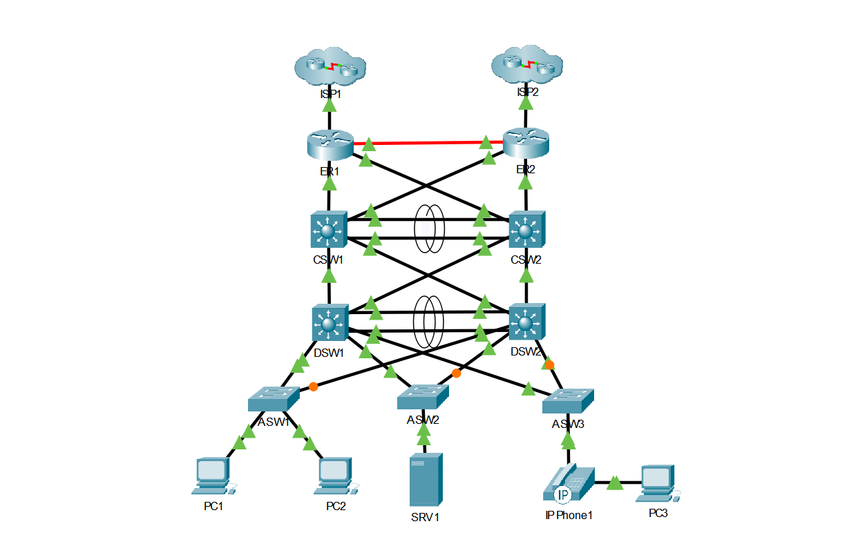
All links between the ISP and Edge Routers, and Core and Distribution Switches are layer-3 Point-to-Point /30 networks.
IP addresses were configured on each interface using the ip address 10.x.x.x 255.255.255.252 command from interface configuration mode.
ISP-to-Edge Subnets
ISP-to-Edge Subnets
The IP addressing for the networks configured between the ISP and Edge Routers is as follows:
| Network | Device | Interface | IP Address |
|---|---|---|---|
| 81.220.16.32/30 | ISP1 | G0/0 | 81.220.16.33 |
| 81.220.16.32/30 | ER1 | G0/0 | 81.220.16.34 |
| 203.0.113.0/30 | ISP2 | G0/0 | 203.0.113.1 |
| 203.0.113.0/30 | ER2 | G0/0 | 203.0.113.2 |
Edge-to-Core Subnets
Edge-to-Core Subnets
The IP addressing for the networks configured between the Edge Routers and Core Switches is as follows:
| Network | Device | Interface | IP Address |
|---|---|---|---|
| 10.0.0.0/30 | ER1 | G0/0/0 | 10.0.0.1 |
| 10.0.0.0/30 | ER2 | G0/0/0 | 10.0.0.2 |
| 10.1.1.0/30 | ER1 | G0/1 | 10.1.1.1 |
| 10.1.1.0/30 | CSW1 | G1/0/5 | 10.1.1.2 |
| 10.1.1.4/30 | ER1 | G0/2 | 10.1.1.5 |
| 10.1.1.4/30 | CSW2 | G1/0/5 | 10.1.1.6 |
| 10.1.1.8/30 | ER2 | G0/1 | 10.1.1.9 |
| 10.1.1.8/30 | CSW1 | G1/0/6 | 10.1.1.10 |
| 10.1.1.12/30 | ER2 | G0/2 | 10.1.1.13 |
| 10.1.1.12/30 | CSW2 | G1/0/6 | 10.1.1.14 |
Core-to-Distribution Subnets
Core-to-Distribution Subnets
The IP addressing for the networks configured between the Core Switches and Distribution Switches is as follows:
| Network | Device | Interface | IP Address |
|---|---|---|---|
| 10.2.2.16/30 | CSW1 | Po1 | 10.2.2.17 |
| 10.2.2.16/30 | CSW2 | Po1 | 10.2.2.18 |
| 10.2.2.20/30 | CSW1 | G1/0/3 | 10.2.2.21 |
| 10.2.2.20/30 | DSW1 | G1/0/6 | 10.2.2.22 |
| 10.2.2.24/30 | CSW1 | G1/0/4 | 10.2.2.25 |
| 10.2.2.24/30 | DSW2 | G1/0/6 | 10.2.2.26 |
| 10.2.2.28/30 | CSW2 | G1/0/3 | 10.2.2.29 |
| 10.2.2.28/30 | DSW1 | G1/0/7 | 10.2.2.30 |
| 10.2.2.32/30 | CSW2 | G1/0/4 | 10.2.2.33 |
| 10.2.2.32/30 | DSW2 | G1/0/7 | 10.2.2.34 |
VLAN Subnets
VLAN Subnets
The IP addressing for each VLAN is as follows:
| VLAN | Network | Default Gateway |
|---|---|---|
| 10 | 10.0.10.0/24 | 10.0.10.1 |
| 20 | 10.0.20.0/24 | 10.0.20.1 |
| 30 | 10.0.30.0/24 | 10.0.30.1 |
| 99 | 10.0.99.0/28 | 10.0.99.1 |
Loopback Interface Addressing
Loopback Interface Addressing
To provide a stable interface that remains up and doesn’t rely on hardware, I configured loopback interfaces on all layer-3 devices.
Each ISP Router is configured with the loopback address 8.8.8.8/32 which will be used to simulate and test internet connectivity from the LAN.
Each Edge Router, Core, and Distribution Switch’s loopback interfaces have been configured with an address from the 10.255.0.0/29 block.
Loopback interfaces were created by issuing the interface loopback 0 command from global configuration mode
Each Loopback interface was assigned an IP address by issuing the ip address 10.255.0.x 255.255.255.255 command from loopback interface configuration mode.
The loopback IP assignments are as follows:
| Device | Interface | IP Address |
|---|---|---|
| ISP1 | Loopback 0 | 8.8.8.8/32 |
| ISP2 | Loopback 0 | 8.8.8.8/32 |
| ER1 | Loopback 0 | 10.255.0.1/32 |
| ER2 | Loopback 0 | 10.255.0.2/32 |
| CSW1 | Loopback 0 | 10.255.0.3/32 |
| CSW2 | Loopback 0 | 10.255.0.4/32 |
| DSW1 | Loopback 0 | 10.255.0.5/32 |
| DSW2 | Loopback 0 | 10.255.0.6/32 |
Access Switch Addressing
Access Switch Addressing
For remote management purposes, each Access Switch’s VLAN 99 (Management) interface is configured with an IP address from the 10.0.99.0/28 network.
The default gateway of 10.0.99.1 was configured on each Access Switch using the ip default-gateway 10.0.99.1 command from global configuration mode.
The IP addressing for Access Switches VLAN 99 Interfaces is as follows:
| Device | Interface | IP Address | Default Gateway |
|---|---|---|---|
| ASW1 | VLAN 99 | 10.0.99.4/28 | 10.0.99.1 |
| ASW2 | VLAN 99 | 10.0.99.5/28 | 10.0.99.1 |
| ASW3 | VLAN 99 | 10.0.99.6/28 | 10.0.99.1 |
Here’s a partial output of the running configuration on ASW1 verifying the default gateway and IP address configurations:
!
interface Vlan99
 ip address 10.0.99.4 255.255.255.240
!
ip default-gateway 10.0.99.1
!
HSRPv2
Enabling HSRPv2
Enabling HSRPv2
For gateway redundancy, the Distribution Switches SVI interfaces are paired into HSRP groups.
I enabled HSRPv2 for each SVI by issuing the standby version 2 command in vlan interface configuration mode.
Virtual Gateway IP
Virtual Gateway IP
This virtual IP address of each group will act as the default gateway for each VLAN and will be advertised to clients via DHCP (See DHCP section for more information).
I configured the virtual IP to be the first usable IP address in the subnet using the standby x ip x.x.x.x where x is the group number and x.x.x.x is the virtual IP address.
Priority & Preemption
Adjusting Priority
To make DSW1 the active router in each group I increased its priority to 105 using the standby x priority 105 command in interface configuration mode, where x is the group number.
I also enabled preemption for each group on DSW1 to ensure it is always the active router by issuing the standby x preempt command in interface configuration mode, where x is the group number.
Verifying HSRP Configuration
Verifying HSRP Configuration
Here is the output of the show standby brief command on DSW1 verifying the virtual IP assignments and priority adjustments configured above:
DSW1#show standby brief
                     P indicates configured to preempt.
                     |
Interface   Grp  Pri P State    Active          Standby         Virtual IP
Vl10        10   105 P Active   local           10.0.10.2       10.0.10.1
Vl20        20   105 P Active   local           10.0.20.2       10.0.20.1
Vl30        30   105 P Active   local           10.0.30.2       10.0.30.1
Vl99        99   105 P Active   local           10.0.99.2       10.0.99.1
OSPF & Static Routes
Single Area OSPF
Single Area OSPF
Dynamic routing protocols allow us to propagate network routes to neighboring devices, saving us the hassle of manual static configuration.
In this network, Single area OSPF (area 0) is enabled on each Edge Router, Core, and Distribution Switch using the router OSPF 1 command from global configuration mode.
Network Commands
Network Commands
From router configuration mode, each interface was activated using the most specific network x.x.x.x y.y.y.y area 0 commands, where x.x.x.x is the network address and y.y.y.y is the exact wildcard mask.
Here’s a partial output of the running configuration on CSW1 which displays the network commands issued from router configuration mode:
router ospf 1
 network 10.2.2.16 0.0.0.3 area 0
 network 10.2.2.20 0.0.0.3 area 0
 network 10.2.2.24 0.0.0.3 area 0
 network 10.1.1.0 0.0.0.3 area 0
 network 10.1.1.8 0.0.0.3 area 0
 network 10.255.0.3 0.0.0.0 area 0
Passive-Interfaces
Passive-Interfaces
To reduce unnecessary OSPF traffic all loopback interfaces were configured as passive using the passive-interface loopback 0 command from router configuration mode.
Additionally, all Distribution Switch interfaces connected to Access Switches have been configured as passive.
Here’s a partial output of the show ip protocols command on DSW1 showing the passive interface configurations:
DSW1(config-router)#do show ip protocols

Routing Protocol is "ospf 1"
  Passive Interface(s):
    GigabitEthernet1/0/3
    GigabitEthernet1/0/4
    GigabitEthernet1/0/5
    Loopback0
Router-IDs
Router-IDs
Each device’s OSPF router-ID is manually configured to match the loopback interface IP using the router-id command from router configuration mode.
Note that with the absence of a manually configured router-ID, OSPF would have used the loopback interface address as its router-ID by default.
Here’s a partial output of the show ip protocols command on ER1 showing the Router-ID configurations:
ER1(config-if)#do show ip protocols

Routing Protocol is "ospf 1"
  Routing Information Sources:
    Gateway         Distance      Last Update
    10.255.0.1           110      00:16:07
    10.255.0.2           110      00:16:08
    10.255.0.3           110      00:15:33
    10.255.0.4           110      00:15:33
    10.255.0.5           110      00:02:46
    10.255.0.6           110      00:02:46
  Distance: (default is 110)
Point-to-Point Network Type
Point-to-Point Network Type
Later during the project I chose to disable DR/BDR elections and further reduce OSPF overhead traffic by configuring all OSPF enabled interfaces to use the Point-to-Point OSPF network type (instead of the default Broadcast network type).
This was configured by issuing the ip ospf network point-to-point command from interface configuration mode.
The layer-3 EtherChannel between the Core Switches was left using the default Broadcast network type. This is due to known issues associated with EtherChannels and the P2P OSPF network type.
Here’s the output of the show ip ospf interface brief command on CSW1:
CSW1#show ip ospf interface brief
Interface     PID   Area                     IP Address/Mask          Cost  State  Nbrs F/C
Lo0             1   0                     10.255.0.3/255.255.255.255   1     WAIT  0/0
Gig1/0/6        1   0                      10.1.1.10/255.255.255.252   1    POINT  0/0
Gig1/0/4        1   0                      10.2.2.25/255.255.255.252   1    POINT  0/0
Gig1/0/5        1   0                       10.1.1.2/255.255.255.252   1    POINT  0/0
Gig1/0/3        1   0                      10.2.2.21/255.255.255.252   1    POINT  0/0
Po1             1   0                      10.2.2.17/255.255.255.252   1      BDR  0/0
Default Static Routes
Default Static Routes
A defualt static route for ISP1 is configured on ER1 and a default static route for ISP2 is configured on ER2 using the ip route 0.0.0.0 0.0.0.0 x.x.x.x where x.x.x.x is the next hop IP address.
These default static routes will cause the Edge routers to route all traffic that doesn’t match a known route in the routing table to the ISP Routers.
Floating Static Routes
Floating Static Routes
In case the default static routes pointing from the Edge Routers to the ISP routers fail, the Edge Routers are configured with a backup, floating static route pointing to the neighboring Edge Router.
More specifically, a floating static route pointing to ER2 is configured on ER1 and vise-versa using the ip route 0.0.0.0 0.0.0.0 x.x.x.x 10 where x.x.x.x is the IP address of the other Edge Router and 10 is the administrative distance.
This ensures that if either Edge Routers WAN interface goes down, and the primary default route is removed from the routing table, the floating static route will be inserted into the routing table and will route all traffic destined for an unkown network to the neighboring Edge Router. The neighboring edge router will then route that traffice to the ISP Router using its default static route.
Here’s a simulated failover example of ER1 replacing its default route with the floating static route after shutting down ER1’s g0/0 WAN interface (the interface connected to ISPR1):
ER1(config)#ip route 0.0.0.0 0.0.0.0 10.0.0.2 10
ER1(config)#int g0/0
ER1(config-if)#shut
ER1(config-if)#
%LINK-5-CHANGED: Interface GigabitEthernet0/0, changed state to administratively down

%LINEPROTO-5-UPDOWN: Line protocol on Interface GigabitEthernet0/0, changed state to down

ER1(config-if)#do sh ip route

Gateway of last resort is 10.0.0.2 to network 0.0.0.0

ER1(config-if)#do ping 8.8.8.8

Type escape sequence to abort.
Sending 5, 100-byte ICMP Echos to 8.8.8.8, timeout is 2 seconds:
!!!!!
Success rate is 100 percent (5/5), round-trip min/avg/max = 0/0/0 ms
Propagating The Default Route
Propagating The Default Route
I used the Default Information Originate command on both ER1 and ER2 to propagate their default routes through the network.
Though this allows for equal-cost load balancing of all internet-bound traffic from the LAN, it is not an intelligent failover solution.
If one ISP goes down but the Edge Router’s WAN interface stays up, OSPF has no way of knowing. It will continue to advertise the default route, and traffic will begin to flow into a black hole.
A more intelligent solution would be to configure IP SLA and tracking on each Edge Router to monitor the reachablility to and from the internet. This would allow failover even if the link between the Edge Router and ISP Router remained up.
However, this is outside of the scope of the CCNA and is not supported in Packet Tracer.
Verifying OSPF Configurations
Verifying OSPF Configurations
Using the show ip route command on ER1, we can see OSPF has completely populated the routing table successfully:
ER1#show ip route
Codes: L - local, C - connected, S - static, R - RIP, M - mobile, B - BGP
       D - EIGRP, EX - EIGRP external, O - OSPF, IA - OSPF inter area
       N1 - OSPF NSSA external type 1, N2 - OSPF NSSA external type 2
       E1 - OSPF external type 1, E2 - OSPF external type 2, E - EGP
       i - IS-IS, L1 - IS-IS level-1, L2 - IS-IS level-2, ia - IS-IS inter area
       * - candidate default, U - per-user static route, o - ODR
       P - periodic downloaded static route

Gateway of last resort is 81.220.16.33 to network 0.0.0.0

     10.0.0.0/8 is variably subnetted, 23 subnets, 3 masks
C       10.0.0.0/30 is directly connected, GigabitEthernet0/0/0
L       10.0.0.1/32 is directly connected, GigabitEthernet0/0/0
O       10.0.10.0/24 [110/3] via 10.1.1.2, 00:12:59, GigabitEthernet0/1
                     [110/3] via 10.1.1.6, 00:12:59, GigabitEthernet0/2
O       10.0.20.0/24 [110/3] via 10.1.1.2, 00:12:59, GigabitEthernet0/1
                     [110/3] via 10.1.1.6, 00:12:59, GigabitEthernet0/2
O       10.0.30.0/24 [110/3] via 10.1.1.2, 00:13:09, GigabitEthernet0/1
                     [110/3] via 10.1.1.6, 00:13:09, GigabitEthernet0/2
O       10.0.99.0/24 [110/3] via 10.1.1.2, 00:13:09, GigabitEthernet0/1
                     [110/3] via 10.1.1.6, 00:13:09, GigabitEthernet0/2
C       10.1.1.0/30 is directly connected, GigabitEthernet0/1
L       10.1.1.1/32 is directly connected, GigabitEthernet0/1
C       10.1.1.4/30 is directly connected, GigabitEthernet0/2
L       10.1.1.5/32 is directly connected, GigabitEthernet0/2
O       10.1.1.8/30 [110/2] via 10.1.1.2, 00:13:34, GigabitEthernet0/1
                    [110/2] via 10.0.0.2, 00:13:34, GigabitEthernet0/0/0
O       10.1.1.12/30 [110/2] via 10.1.1.6, 00:13:34, GigabitEthernet0/2
                     [110/2] via 10.0.0.2, 00:13:34, GigabitEthernet0/0/0
O       10.2.2.16/30 [110/2] via 10.1.1.2, 00:13:09, GigabitEthernet0/1
                     [110/2] via 10.1.1.6, 00:13:09, GigabitEthernet0/2
O       10.2.2.20/30 [110/2] via 10.1.1.2, 00:13:34, GigabitEthernet0/1
O       10.2.2.24/30 [110/2] via 10.1.1.2, 00:13:34, GigabitEthernet0/1
O       10.2.2.28/30 [110/2] via 10.1.1.6, 00:13:34, GigabitEthernet0/2
O       10.2.2.32/30 [110/2] via 10.1.1.6, 00:13:34, GigabitEthernet0/2
C       10.255.0.1/32 is directly connected, Loopback0
O       10.255.0.2/32 [110/2] via 10.0.0.2, 00:13:34, GigabitEthernet0/0/0
O       10.255.0.3/32 [110/2] via 10.1.1.2, 00:13:34, GigabitEthernet0/1
O       10.255.0.4/32 [110/2] via 10.1.1.6, 00:13:34, GigabitEthernet0/2
O       10.255.0.5/32 [110/3] via 10.1.1.2, 00:13:34, GigabitEthernet0/1
                      [110/3] via 10.1.1.6, 00:13:34, GigabitEthernet0/2
O       10.255.0.6/32 [110/3] via 10.1.1.2, 00:13:34, GigabitEthernet0/1
                      [110/3] via 10.1.1.6, 00:13:34, GigabitEthernet0/2
     81.0.0.0/8 is variably subnetted, 2 subnets, 2 masks
C       81.220.16.32/30 is directly connected, GigabitEthernet0/0
L       81.220.16.34/32 is directly connected, GigabitEthernet0/0
S*   0.0.0.0/0 [1/0] via 81.220.16.33
DHCP
Selecting the DHCP Server
Selecting the DHCP Server
For the purposes of showcasing my CCNA skills, ER1 is configured as the centralized DHCP server for the network.
Address Exclusions
Address Exclusions
The first 10 addresses of each network were excluded from the lease pool using the ip dhcp excluded-address x.x.x.x y.y.y.y command from global configuration mode. Where x.x.x.x is the low address in the exclusion range and y.y.y.y is the high address.
Here’s the output from the running configuration on ER1:
!
ip dhcp excluded-address 10.0.10.1 10.0.10.10
ip dhcp excluded-address 10.0.20.1 10.0.20.10
ip dhcp excluded-address 10.0.30.1 10.0.30.10
ip dhcp excluded-address 10.0.99.1 10.0.99.10
!
DHCP Pools
Configuring DHCP Pools
DHCP pools for each VLAN’s /24 network were created using the ip dhcp pool x command, where x is the name of the pool.
The network for each pool was defined using the network x.x.x.x y.y.y.y command where x.x.x.x is the network address and y.y.y.y is the subnet mask.
The default gateway for each pool is the first usable IP of each VLAN’s subnet which is the Virtual IP of each HSRP group. The default router for each pool was configured using the default-router x.x.x.x command from dhcp configuration mode.
The DNS server for each pool was configured using the dns-server 10.0.30.5 command from dhcp configuration mode.
The domain name for each pool was configured using the domain-name aiken.com command from dhcp configuration mode.
Here’s the configuration of DHCP pools as shown in the running configuration on ER1:
!
ip dhcp pool vlan10
 network 10.0.10.0 255.255.255.0
 default-router 10.0.10.1
 dns-server 10.0.30.5
 domain-name aiken.com
ip dhcp pool vlan20
 network 10.0.20.0 255.255.255.0
 default-router 10.0.20.1
 dns-server 10.0.30.5
 domain-name aiken.com
ip dhcp pool vlan30
 network 10.0.30.0 255.255.255.0
 default-router 10.0.30.1
 dns-server 10.0.30.5
 domain-name aiken.com
!
DHCP Relay
DHCP Relay
Each Distribution Switch’s SVI interface is configured with ip helper-address 10.255.0.1 command from interface configuration mode. 10.255.0.1 is the loopback address of ER1.
This will allow the Distribution Switches to relay DHCP Discover messages to ER1, the DHCP server, which is on a different network.
Here is the DHCP Helper-address configuration shown in the running configuration on DSW1:
!
interface Vlan10
 mac-address 0001.43e7.9301
 ip address 10.0.10.2 255.255.255.0
 ip helper-address 10.255.0.1
 standby version 2
 standby 10 ip 10.0.10.1
 standby 10 priority 105
 standby 10 preempt
!
Verifying DHCP Services
Verifying DHCP Services
Here we can see PC1 successfully recieving an IP configuration from the DHCP server after issuing the ipconfig /renew command in the command prompt:
C:\>ipconfig /renew

   IP Address......................: 10.0.10.11
   Subnet Mask.....................: 255.255.255.0
   Default Gateway.................: 10.0.10.1
   DNS Server......................: 10.0.30.5
DNS
Selecting the DNS Sever
Selecting the DNS Server
SRV1 is configured as the DNS server for this network and has been statically assigned the IP address of 10.0.30.5 with a mask of 255.255.255.0.
A-records
A-records
I entered a single A-record for google.com at 8.8.8.8 for testing name resolution.
Verifying DNS Services
Verifying DNS Services
Here we can see PC2 successfully use the DNS server to resolve google.com to 8.8.8.8:
C:\>ping google.com

Pinging 8.8.8.8 with 32 bytes of data:

Request timed out.
Reply from 8.8.8.8: bytes=32 time<1ms TTL=252
Reply from 8.8.8.8: bytes=32 time<1ms TTL=252
Reply from 8.8.8.8: bytes=32 time<1ms TTL=252

Ping statistics for 8.8.8.8:
    Packets: Sent = 4, Received = 3, Lost = 1 (25% loss),
Approximate round trip times in milli-seconds:
    Minimum = 0ms, Maximum = 0ms, Average = 0ms
NTP
Setting Date & Time
Setting Date & Time
I set the date and time on ER1 using the clock set 05:35:00 June 16 2025 command from priviledge EXEC mode.
To update the hardware clock of the devices I executed the ntp update-calendar command from global configuration mode.
Here’s the output of the show clock command on ER1
ER1#show clock
05:35:37.203 EST Mon Jun 16 2025
Configuring NTP Servers
Configuring NTP Servers
I configured ER1 as an NTP server using the ntp master 5 command from global configuration mode. Where 5 is the stratum.
NTP Authentication
NTP Authentication
For security, I configured NTP authentication.
First, I enabled it with the ntp authentication command from global configuration mode.
Then, I created the NTP authentication key with the ntp authentication-key 1 md5 cisco command, where cisco is the key.
Finally, I enabled the key with ntp trusted-key 1
Configuring NTP Clients
Configuring NTP Clients
I configured all remaining Core, Distribution and Access Switches as NTP clients.
I created the cisco authentication key (as mentioned in the NTP Authentication section) and specified ER1’s loopback address as the NTP server using the ntp server 10.255.0.1 key 1 command from global configuration mode.
Verifying NTP Configuration
Verifying NTP Configuration
Here is the output of the NTP configuration in the running configuration on CSW1:
!
ntp authentication-key 1 md5 0822455D0A16 7
ntp authenticate
ntp trusted-key 1
ntp server 10.255.0.1 key 1
!
Additionally, here is the output of the show ntp associations command on CSW1:
CSW1#show ntp associations

address         ref clock       st   when     poll    reach  delay          offset            disp
 ~10.255.0.1    .STEP.          16   1.74997e+0964      0      0.00           0.00              0.48
*~10.1.1.1      127.127.1.1     5    9        16      377    0.00           2.00              0.12
 * sys.peer, # selected, + candidate, - outlyer, x falseticker, ~ configured
NAT & PAT
Configuring an Extended ACL
Configuring an Extended ACL
To specify which addresses should be translated, an extended access-list named pat has been configured using the ip access-list extended pat command from global configuration mode on ER1.
Permit Access List Entries for each /24 VLAN network were created using the permit ip x.x.x.x y.y.y.y any command from named access list configuration mode. Where x.x.x.x is the source ip and y.y.y.y is the wildcard mask. The word any at the end of the command specifies any destination.
Here is the pat access list configuration as shown in the running configuration on ER1:
!
ip access-list extended pat
 permit ip 10.0.10.0 0.0.0.255 any
 permit ip 10.0.20.0 0.0.0.255 any
 permit ip 10.0.30.0 0.0.0.255 any
!
Inside & Outside Interfaces
Inside & Outside Interfaces
Interface G0/0 was configured with the ip nat outside command from interface configuration mode.
Interfaces G0/1 and G0/2 were configured with the ip nat inside command from interface configuration mode.
Enabling PAT
Enabling PAT
Finally, NAT Overload (PAT) was enabled by executing the ip nat inside source list pat interface GigabitEthernet0/0 overload command from global configuration mode.
Verifying PAT Configuration
Verifying PAT Configuration
After pinging 8.8.8.8 from PC2, here is the output of the show ip nat translations command on ER1:
ER1#show ip nat translations
Pro  Inside global     Inside local       Outside local      Outside global
icmp 81.220.16.34:10   10.0.10.14:10      8.8.8.8:10         8.8.8.8:10
CDP & LLDP
Enabling CDP & LLDP
Enabling CDP & LLDP
Both CDP and LLDP are enabled globally on each Edge Router, Core, Distribution, and Access Switch using the cdp run and lldp run commands from global configuration mode.
Identifying Devices
Identifying Devices
CDP operates at layer 2, making it useful for identifying which devices are connected to which interfaces when configuring IP addressing.
Here is the output of the show cdp neighbors command on DSW1:
DSW1#show cdp neighbors
Capability Codes: R - Router, T - Trans Bridge, B - Source Route Bridge
                  S - Switch, H - Host, I - IGMP, r - Repeater, P - Phone
Device ID    Local Intrfce   Holdtme    Capability   Platform    Port ID
CSW1         Gig 1/0/6        166                    3650        Gig 1/0/3
CSW2         Gig 1/0/7        159                    3650        Gig 1/0/3
ASW2         Gig 1/0/4        84             S       2960        Gig 0/1
ASW3         Gig 1/0/5        146            S       2960        Gig 0/1
ASW1         Gig 1/0/3        144            S       2960        Gig 0/1
Verifying CDP & LLDP Configurations
Verifying CDP & LLDP Configurations
Here, on CSW1, we can see CDP is enabled globally in the output of the show cdp command.
CSW1#show cdp
Global CDP information:
    Sending CDP packets every 60 seconds
    Sending a holdtime value of 180 seconds
    Sending CDPv2 advertisements is enabled
Additionally, we can see the same for LLDP in the output of the show lldp command.
CSW1#show lldp
Global LLDP Information:
    Status: ACTIVE
    LLDP advertisements are sent every 30 seconds
    LLDP hold time advertised is 120 seconds
    LLDP interface reinitialisation delay is 2 seconds
DHCP Snooping
Enabling DHCP Snooping
Enabling DHCP Snooping
DHCP Snooping is enabled for VLANS 1-1000 on all access switches using the ip dhcp snooping vlan 1-1000 from global configuration mode.
Trusted Interfaces
Trusted Interfaces
The interfaces on each Access Switch connected to a Distribution Switch have been configured as trusted ports using the ip dhcp snooping trust command from interface configuration mode.
Disabling Option 82
Disabling Option 82
The Information Option 82 has been disabled since the Access Switches are not acting as DHCP relay agents. If left enabled, DHCP requests received by the Distribution and Core Switches on untrusted ports will drop DHCP Discover messages.
Information Option 82 was disabled by executing the no ip dhcp snooping information option
DHCP Rate Limiting
DHCP Rate Limiting
To protect against DHCP Exhaustion attacks, a limit of 15 packets per second has been configured on all untrusted ports using the ip dhcp snooping limit rate 15 command from interface configuration mode.
Verifying DHCP Snooping Configuration
Verifying DHCP Snooping Configuration
I issued the ipconfig /renew command on PC1 and PC2.
Here is the output of the show ip dhcp snooping binding command on ASW1:
ASW1#show ip dhcp snooping binding
MacAddress          IpAddress        Lease(sec)  Type           VLAN  Interface
------------------  ---------------  ----------  -------------  ----  -----------------
00:01:43:34:45:80   10.0.10.12       0           dhcp-snooping  10    FastEthernet0/1
00:D0:BA:89:DA:75   10.0.10.11       0           dhcp-snooping  10    FastEthernet0/2
Total number of bindings: 2
Finally, here is the output of the show ip dhcp snooping command on ASW1:
ASW1(config)#do sh ip dhcp snoop
Switch DHCP snooping is enabled
DHCP snooping is configured on following VLANs:
1-1000
Insertion of option 82 is disabled
Option 82 on untrusted port is not allowed
Verification of hwaddr field is enabled
Interface                  Trusted    Rate limit (pps)
-----------------------    -------    ----------------
FastEthernet0/1            no         15
FastEthernet0/2            no         15
GigabitEthernet0/1         yes        unlimited
GigabitEthernet0/2         yes        unlimited
Dynamic ARP Inspection
Enabling DAI
Enabling DAI
To protect against ARP Poisoning (man-in-the-middle) attacks, Dynamic ARP inspection was enabled globally on all Access Switches using the ip arp inspection vlan 1-1000 from global configuration mode.
Trusted Interfaces
Trusted Interfaces
Each Access Switch port connected to a Distribution Switch was configured as a trusted port using the ip arp inspection trust command from interface configuration mode.
Verifying DAI Configuration
Verifying DAI Configuration
Here is the output of the show ip arp inspection interfaces command on ASW1:
ASW1#show ip arp inspection interfaces
Interface        Trust State     Rate(pps)    Burst Interval
---------------  -----------     ---------    --------------
Fa0/1            Untrusted              15                 1
Fa0/2            Untrusted              15                 1
Fa0/3            Untrusted              15                 1
Fa0/4            Untrusted              15                 1
Fa0/5            Untrusted              15                 1
Fa0/6            Untrusted              15                 1
Fa0/7            Untrusted              15                 1
Fa0/8            Untrusted              15                 1
Fa0/9            Untrusted              15                 1
Fa0/10           Untrusted              15                 1
Fa0/11           Untrusted              15                 1
Fa0/12           Untrusted              15                 1
Fa0/13           Untrusted              15                 1
Fa0/14           Untrusted              15                 1
Fa0/15           Untrusted              15                 1
Fa0/16           Untrusted              15                 1
Fa0/17           Untrusted              15                 1
Fa0/18           Untrusted              15                 1
Fa0/19           Untrusted              15                 1
Fa0/20           Untrusted              15                 1
Fa0/21           Untrusted              15                 1
Fa0/22           Untrusted              15                 1
Fa0/23           Untrusted              15                 1
Fa0/24           Untrusted              15                 1
Gig0/1           Trusted                15                 1
Gig0/2           Trusted                15                 1
Port Security
Enabling Port Security
Enabling Port Security
To keep unknown devices from accessing the physical network, Port Security has been enabled on all Access Switch Access Ports using the switchport port-security command from interface configuration mode.
Sticky MAC Addresses
Sticky MAC Addresses
To add end host MAC addresses to the running configuration, the command switchport port-security mac-address sticky command was executed in interface configuration mode.
After pinging 8.8.8.8 from PC1, its MAC-address was added to the running configuration of ASW1.
Here is interface fa0/1’s configuration as shown in the running configuration:
interface FastEthernet0/1
 switchport access vlan 10
 ip dhcp snooping limit rate 15
 switchport mode access
 switchport port-security
 switchport port-security mac-address sticky
 switchport port-security mac-address sticky 0001.4334.4580
Triggering Port Security
Triggering Port Security
To trigger port security, I disconnected PC1 from ASW1’s F0/1 interface and connected a new PC.
Unfortunalty, the port does not enter an err-disabled state in Packet Tracer.
However, In the output of the show port-security interface fa0/1 command we can see the port status is now secure-shutdown and the Security violation Count is now 1.
ASW1(config-if)#do sh port-sec int fa0/1
Port Security              : Enabled
Port Status                : Secure-shutdown
Violation Mode             : Shutdown
Aging Time                 : 0 mins
Aging Type                 : Absolute
SecureStatic Address Aging : Disabled
Maximum MAC Addresses      : 1
Total MAC Addresses        : 1
Configured MAC Addresses   : 0
Sticky MAC Addresses       : 1
Last Source Address:Vlan   : 00D0.D3AC.07A8:10
Security Violation Count   : 1
Verifying Port Security Configuration
Verifying Port Security Configuration
Here is the output of the show port-security command on ASW1:
Secure Port MaxSecureAddr CurrentAddr SecurityViolation Security Action
               (Count)       (Count)        (Count)
--------------------------------------------------------------------
        Fa0/1        1          1                 0         Shutdown
        Fa0/2        1          0                 0         Shutdown
        Fa0/3        1          0                 0         Shutdown
        Fa0/4        1          0                 0         Shutdown
        Fa0/5        1          0                 0         Shutdown
        Fa0/6        1          0                 0         Shutdown
        Fa0/7        1          0                 0         Shutdown
        Fa0/8        1          0                 0         Shutdown
        Fa0/9        1          0                 0         Shutdown
       Fa0/10        1          0                 0         Shutdown
       Fa0/11        1          0                 0         Shutdown
       Fa0/12        1          0                 0         Shutdown
       Fa0/13        1          0                 0         Shutdown
       Fa0/14        1          0                 0         Shutdown
       Fa0/15        1          0                 0         Shutdown
       Fa0/16        1          0                 0         Shutdown
       Fa0/17        1          0                 0         Shutdown
       Fa0/18        1          0                 0         Shutdown
       Fa0/19        1          0                 0         Shutdown
       Fa0/20        1          0                 0         Shutdown
       Fa0/21        1          0                 0         Shutdown
       Fa0/22        1          0                 0         Shutdown
       Fa0/23        1          0                 0         Shutdown
       Fa0/24        1          0                 0         Shutdown
----------------------------------------------------------------------
SSH
Genrating Keys
Genrating Keys
RSA key-pairs were generated for each device using the crypto key generate rsa command from global configuration mode.
A modulus size of 1024 was specified.
Version 2
Version 2
SSH Version 2 was enable for each device using the ip ssh version 2 command from global configuration mode.
Configuring VTY Lines
Configuring VTY Lines
The VTY lines for each device were configured by enter VTY line configuration mode using the line vty 0 15 command from global configuration mode.
Telnet was disabled by issuing the transport input ssh command in line configuration mode.
Local user authentication was specified by issuing login local command in line configuration mode.
Verifying Remote Managability
Verifying Remote Managability
Here is an example of SSH’ing into ASW1 from DSW1:
DSW1>ssh -l aiken 10.0.99.4

Password:

ASW1>
Syslog
Enabling Time Stamps
Enabling Time Stamps
To show the date and time for syslog messages, I issued the service timestamps log datetime msec command from global configuration mode.
Here we can see the date and time shown in the output of a syslog message generated on ER1:
ER1(config)#service timestamps log datetime msec
ER1(config)#exit
ER1#
*Jun 16, 06:01:31.011: SYS-5-CONFIG_I: Configured from console by console
ER1#
Configuring the Syslog Server
Configuring the Syslog Server
SRV1 has been configured as the Syslog server.
First, I enabled Syslog services on SRV1, which is a button click in Packet Tracer.
Then, I issued the logging host 10.0.30.5 command from global configuration mode.
Here’s the output of the show logging command on ER1:
ER1#show logging
Syslog logging: enabled (0 messages dropped, 0 messages rate-limited,
        0 flushes, 0 overruns, xml disabled, filtering disabled)

No Active Message Discriminator.


No Inactive Message Discriminator.


  Console logging: level debugging, 12 messages logged, xml disabled,
        filtering disabled
  Monitor logging: level debugging, 12 messages logged, xml disabled,
        filtering disabled
  Buffer logging:  level debugging, 0 messages logged, xml disabled,
        filtering disabled

  Logging Exception size (4096 bytes)
  Count and timestamp logging messages: disabled
  Persistent logging: disabled

No active filter modules.

ESM: 0 messages dropped
  Trap logging: level debugging, 12 message lines logged
      Logging to 10.0.30.5  (udp port 514,  audit disabled,
           authentication disabled, encryption disabled, link up),
           2 message lines logged,
           0 message lines rate-limited,
           0 message lines dropped-by-MD,
           xml disabled, sequence number disabled
           filtering disabled
Full Device Configurations
ER1
ER1 Running Configuration
ER1#show run
Building configuration...

Current configuration : 2695 bytes
!
version 15.1
service timestamps log datetime msec
no service timestamps debug datetime msec
no service password-encryption
!
hostname ER1
!
!
!
enable secret 5 $1$mERr$hx5rVt7rPNoS4wqbXKX7m0
!
!
ip dhcp excluded-address 10.0.10.1 10.0.10.10
ip dhcp excluded-address 10.0.20.1 10.0.20.10
ip dhcp excluded-address 10.0.30.1 10.0.30.10
ip dhcp excluded-address 10.0.99.1 10.0.99.10
!
ip dhcp pool vlan10
 network 10.0.10.0 255.255.255.0
 default-router 10.0.10.1
 dns-server 10.0.30.5
 domain-name aiken.com
ip dhcp pool vlan20
 network 10.0.20.0 255.255.255.0
 default-router 10.0.20.1
 dns-server 10.0.30.5
 domain-name aiken.com
ip dhcp pool vlan30
 network 10.0.30.0 255.255.255.0
 default-router 10.0.30.1
 dns-server 10.0.30.5
 domain-name aiken.com
clock timezone EST -5
!
!
!
!
no ip cef
no ipv6 cef
!
!
!
username aiken secret 5 $1$mERr$hx5rVt7rPNoS4wqbXKX7m0
!
!
license udi pid CISCO2911/K9 sn FTX152400MB-
!
!
!
lldp run
!
!
!
!
!
!
!
ip ssh version 2
no ip domain-lookup
ip domain-name aiken.com
!
!
spanning-tree mode pvst
!
!
!
!
!
!
interface Loopback0
 ip address 10.255.0.1 255.255.255.255
!
interface GigabitEthernet0/0
 ip address 81.220.16.34 255.255.255.252
 ip nat outside
 duplex auto
 speed auto
!
interface GigabitEthernet0/1
 ip address 10.1.1.1 255.255.255.252
 ip ospf network point-to-point
 ip ospf priority 1
 ip nat inside
 duplex auto
 speed auto
!
interface GigabitEthernet0/2
 ip address 10.1.1.5 255.255.255.252
 ip ospf network point-to-point
 ip ospf priority 1
 ip nat inside
 duplex auto
 speed auto
!
interface GigabitEthernet0/0/0
 ip address 10.0.0.1 255.255.255.252
 ip ospf network point-to-point
 ip ospf priority 1
 standby version 2
!
interface GigabitEthernet0/1/0
 no ip address
 shutdown
!
interface Vlan1
 no ip address
 shutdown
!
router ospf 1
 router-id 10.255.0.1
 log-adjacency-changes
 passive-interface Loopback0
 network 10.1.1.0 0.0.0.3 area 0
 network 10.1.1.4 0.0.0.3 area 0
 network 10.255.0.1 0.0.0.0 area 0
 network 10.0.0.0 0.0.0.3 area 0
 default-information originate
!
ip nat inside source list pat interface GigabitEthernet0/0 overload
ip classless
ip route 0.0.0.0 0.0.0.0 81.220.16.33
ip route 0.0.0.0 0.0.0.0 10.0.0.2 10
!
ip flow-export version 9
!
!
ip access-list extended pat
 permit ip 10.0.10.0 0.0.0.255 any
 permit ip 10.0.20.0 0.0.0.255 any
 permit ip 10.0.30.0 0.0.0.255 any
!
!
!
!
!
logging trap debugging
logging 10.0.30.5
line con 0
 exec-timeout 20 0
 logging synchronous
!
line aux 0
!
line vty 0 4
 login local
 transport input ssh
line vty 5 15
 login local
 transport input ssh
!
!
ntp authentication-key 1 md5 0822455D0A16 7
ntp authenticate
ntp trusted-key 1
ntp master 5
ntp update-calendar
!
end
CSW1
CSW1 Running Configuration
CSW1#show run
Building configuration...

Current configuration : 3608 bytes
!
version 16.3.2
no service timestamps log datetime msec
no service timestamps debug datetime msec
no service password-encryption
!
hostname CSW1
!
!
enable secret 5 $1$mERr$hx5rVt7rPNoS4wqbXKX7m0
!
!
!
!
!
!
no ip cef
ip routing
!
no ipv6 cef
!
!
!
username aiken secret 5 $1$mERr$hx5rVt7rPNoS4wqbXKX7m0
!
!
lldp run
!
!
!
!
!
!
!
!
!
ip ssh version 2
no ip domain-lookup
ip domain-name aiken.com
!
!
spanning-tree mode pvst
!
!
!
!
!
!
interface Loopback0
 ip address 10.255.0.3 255.255.255.255
!
interface Port-channel1
 no switchport
 ip address 10.2.2.17 255.255.255.252
!
interface GigabitEthernet1/0/1
 no switchport
 no ip address
 channel-group 1 mode desirable
 duplex auto
 speed auto
!
interface GigabitEthernet1/0/2
 no switchport
 no ip address
 channel-group 1 mode desirable
 duplex auto
 speed auto
!
interface GigabitEthernet1/0/3
 no switchport
 ip address 10.2.2.21 255.255.255.252
 ip ospf network point-to-point
 ip ospf priority 1
 duplex auto
 speed auto
!
interface GigabitEthernet1/0/4
 no switchport
 ip address 10.2.2.25 255.255.255.252
 ip ospf network point-to-point
 ip ospf priority 1
 duplex auto
 speed auto
!
interface GigabitEthernet1/0/5
 no switchport
 ip address 10.1.1.2 255.255.255.252
 ip ospf network point-to-point
 ip ospf priority 1
 duplex auto
 speed auto
!
interface GigabitEthernet1/0/6
 no switchport
 ip address 10.1.1.10 255.255.255.252
 ip ospf network point-to-point
 ip ospf priority 1
 duplex auto
 speed auto
!
interface GigabitEthernet1/0/7
 switchport mode access
 shutdown
!
interface GigabitEthernet1/0/8
 switchport mode access
 shutdown
!
interface GigabitEthernet1/0/9
 switchport mode access
 shutdown
!
interface GigabitEthernet1/0/10
 switchport mode access
 shutdown
!
interface GigabitEthernet1/0/11
 switchport mode access
 shutdown
!
interface GigabitEthernet1/0/12
 switchport mode access
 shutdown
!
interface GigabitEthernet1/0/13
 switchport mode access
 shutdown
!
interface GigabitEthernet1/0/14
 switchport mode access
 shutdown
!
interface GigabitEthernet1/0/15
 switchport mode access
 shutdown
!
interface GigabitEthernet1/0/16
 switchport mode access
 shutdown
!
interface GigabitEthernet1/0/17
 switchport mode access
 shutdown
!
interface GigabitEthernet1/0/18
 switchport mode access
 shutdown
!
interface GigabitEthernet1/0/19
 switchport mode access
 shutdown
!
interface GigabitEthernet1/0/20
 switchport mode access
 shutdown
!
interface GigabitEthernet1/0/21
 switchport mode access
 shutdown
!
interface GigabitEthernet1/0/22
 switchport mode access
 shutdown
!
interface GigabitEthernet1/0/23
 switchport mode access
 shutdown
!
interface GigabitEthernet1/0/24
 switchport mode access
 shutdown
!
interface GigabitEthernet1/1/1
 switchport mode access
 shutdown
!
interface GigabitEthernet1/1/2
 switchport mode access
 shutdown
!
interface GigabitEthernet1/1/3
 switchport mode access
 shutdown
!
interface GigabitEthernet1/1/4
 switchport mode access
 shutdown
!
interface Vlan1
 no ip address
 shutdown
!
router ospf 1
 router-id 10.255.0.3
 log-adjacency-changes
 passive-interface Loopback0
 network 10.2.2.16 0.0.0.3 area 0
 network 10.2.2.20 0.0.0.3 area 0
 network 10.2.2.24 0.0.0.3 area 0
 network 10.1.1.0 0.0.0.3 area 0
 network 10.1.1.8 0.0.0.3 area 0
 network 10.255.0.3 0.0.0.0 area 0
!
ip classless
!
ip flow-export version 9
!
!
!
!
!
!
!
line con 0
 exec-timeout 20 0
!
line aux 0
!
line vty 0 4
 login local
 transport input ssh
line vty 5 15
 login local
 transport input ssh
!
!
!
ntp authentication-key 1 md5 0822455D0A16 7
ntp authenticate
ntp trusted-key 1
ntp server 10.255.0.1 key 1
!
end
DSW1
DSW1 Running Configuration
DSW1#show run
Building configuration...

Current configuration : 4947 bytes
!
version 16.3.2
no service timestamps log datetime msec
no service timestamps debug datetime msec
no service password-encryption
!
hostname DSW1
!
!
enable secret 5 $1$mERr$hx5rVt7rPNoS4wqbXKX7m0
!
!
!
!
!
!
no ip cef
ip routing
!
no ipv6 cef
!
!
!
username aiken secret 5 $1$mERr$hx5rVt7rPNoS4wqbXKX7m0
!
!
lldp run
!
!
!
!
!
!
!
!
!
ip ssh version 2
no ip domain-lookup
ip domain-name aiken.com
!
!
vtp domain aiken.com
vtp mode transparent
vtp version 2
!
spanning-tree mode rapid-pvst
spanning-tree portfast default
spanning-tree vlan 1-1000 priority 0
!
!
!
!
!
!
vlan 10
 name Computers
!
vlan 20
 name Phones
!
vlan 30
 name Servers
!
vlan 99
 name Management
!
interface Loopback0
 ip address 10.255.0.5 255.255.255.255
!
interface Port-channel1
 switchport trunk native vlan 1000
 switchport trunk allowed vlan 10,20,30,99
 switchport mode trunk
!
interface GigabitEthernet1/0/1
 switchport trunk native vlan 1000
 switchport trunk allowed vlan 10,20,30,99
 switchport mode trunk
 channel-group 1 mode active
!
interface GigabitEthernet1/0/2
 switchport trunk native vlan 1000
 switchport trunk allowed vlan 10,20,30,99
 switchport mode trunk
 channel-group 1 mode active
!
interface GigabitEthernet1/0/3
 switchport trunk native vlan 1000
 switchport trunk allowed vlan 10,20,30,99
 switchport mode trunk
!
interface GigabitEthernet1/0/4
 switchport trunk native vlan 1000
 switchport trunk allowed vlan 10,20,30,99
 switchport mode trunk
!
interface GigabitEthernet1/0/5
 switchport trunk native vlan 1000
 switchport trunk allowed vlan 10,20,30,99
 switchport mode trunk
!
interface GigabitEthernet1/0/6
 no switchport
 ip address 10.2.2.22 255.255.255.252
 ip ospf network point-to-point
 ip ospf priority 1
 duplex auto
 speed auto
!
interface GigabitEthernet1/0/7
 no switchport
 ip address 10.2.2.30 255.255.255.252
 ip ospf network point-to-point
 ip ospf priority 1
 duplex auto
 speed auto
!
interface GigabitEthernet1/0/8
 switchport mode access
 shutdown
!
interface GigabitEthernet1/0/9
 switchport mode access
 shutdown
!
interface GigabitEthernet1/0/10
 switchport mode access
 shutdown
!
interface GigabitEthernet1/0/11
 switchport mode access
 shutdown
!
interface GigabitEthernet1/0/12
 switchport mode access
 shutdown
!
interface GigabitEthernet1/0/13
 switchport mode access
 shutdown
!
interface GigabitEthernet1/0/14
 switchport mode access
 shutdown
!
interface GigabitEthernet1/0/15
 switchport mode access
 shutdown
!
interface GigabitEthernet1/0/16
 switchport mode access
 shutdown
!
interface GigabitEthernet1/0/17
 switchport mode access
 shutdown
!
interface GigabitEthernet1/0/18
 switchport mode access
 shutdown
!
interface GigabitEthernet1/0/19
 switchport mode access
 shutdown
!
interface GigabitEthernet1/0/20
 switchport mode access
 shutdown
!
interface GigabitEthernet1/0/21
 switchport mode access
 shutdown
!
interface GigabitEthernet1/0/22
 switchport mode access
 shutdown
!
interface GigabitEthernet1/0/23
 switchport mode access
 shutdown
!
interface GigabitEthernet1/0/24
 switchport mode access
 shutdown
!
interface GigabitEthernet1/1/1
 switchport mode access
 shutdown
!
interface GigabitEthernet1/1/2
 switchport mode access
 shutdown
!
interface GigabitEthernet1/1/3
 switchport mode access
 shutdown
!
interface GigabitEthernet1/1/4
 switchport mode access
 shutdown
!
interface Vlan1
 no ip address
 shutdown
!
interface Vlan10
 mac-address 0001.43e7.9301
 ip address 10.0.10.2 255.255.255.0
 ip helper-address 10.255.0.1
 standby version 2
 standby 10 ip 10.0.10.1
 standby 10 priority 105
 standby 10 preempt
!
interface Vlan20
 mac-address 0001.43e7.9302
 ip address 10.0.20.2 255.255.255.0
 ip helper-address 10.255.0.1
 standby version 2
 standby 20 ip 10.0.20.1
 standby 20 priority 105
 standby 20 preempt
!
interface Vlan30
 mac-address 0001.43e7.9303
 ip address 10.0.30.2 255.255.255.0
 ip helper-address 10.255.0.1
 standby version 2
 standby 30 ip 10.0.30.1
 standby 30 priority 105
 standby 30 preempt
!
interface Vlan99
 mac-address 0001.43e7.9304
 ip address 10.0.99.2 255.255.255.0
 standby version 2
 standby 99 ip 10.0.99.1
 standby 99 priority 105
 standby 99 preempt
!
router ospf 1
 router-id 10.255.0.5
 log-adjacency-changes
 passive-interface GigabitEthernet1/0/3
 passive-interface GigabitEthernet1/0/4
 passive-interface GigabitEthernet1/0/5
 passive-interface Loopback0
 network 10.2.2.20 0.0.0.3 area 0
 network 10.2.2.28 0.0.0.3 area 0
 network 10.0.10.0 0.0.0.255 area 0
 network 10.0.20.0 0.0.0.255 area 0
 network 10.0.30.0 0.0.0.255 area 0
 network 10.0.99.0 0.0.0.255 area 0
 network 10.255.0.5 0.0.0.0 area 0
!
ip classless
!
ip flow-export version 9
!
!
!
!
!
!
!
line con 0
 exec-timeout 20 0
 logging synchronous
!
line aux 0
!
line vty 0 4
 login local
 transport input ssh
line vty 5 15
 login local
 transport input ssh
!
!
!
ntp authentication-key 1 md5 0822455D0A16 7
ntp authenticate
ntp trusted-key 1
ntp server 10.255.0.2 key 1
!
end
ASW1
ASW1 Running Configuration
ASW1#show run
Building configuration...

Current configuration : 5133 bytes
!
version 15.0
no service timestamps log datetime msec
no service timestamps debug datetime msec
no service password-encryption
!
hostname ASW1
!
enable secret 5 $1$mERr$hx5rVt7rPNoS4wqbXKX7m0
!
!
!
ip ssh version 2
no ip domain-lookup
ip domain-name aiken.com
!
username aiken secret 5 $1$mERr$hx5rVt7rPNoS4wqbXKX7m0
!
vtp domain aiken.com
vtp mode transparent
vtp version 2
!
ip arp inspection vlan 1-1000
!
ip dhcp snooping vlan 1-1000
ip dhcp snooping information option allow-untrusted
no ip dhcp snooping information option
ip dhcp snooping
!
lldp run
!
spanning-tree mode rapid-pvst
spanning-tree portfast default
spanning-tree portfast bpduguard default
spanning-tree extend system-id
!
vlan 10
 name Computers
!
vlan 20
 name Phones
!
vlan 30
 name Servers
!
vlan 99
 name Management
!
interface FastEthernet0/1
 switchport access vlan 10
 ip dhcp snooping limit rate 15
 switchport mode access
 switchport port-security
 switchport port-security mac-address sticky
 switchport port-security mac-address sticky 0001.4334.4580
!
interface FastEthernet0/2
 switchport access vlan 10
 ip dhcp snooping limit rate 15
 switchport mode access
 switchport port-security
 switchport port-security mac-address sticky
 switchport port-security violation restrict
 switchport port-security mac-address sticky 00D0.BA89.DA75
!
interface FastEthernet0/3
 switchport mode access
 switchport port-security
 switchport port-security mac-address sticky
 switchport port-security mac-address sticky 0001.C79A.84DD
 shutdown
!
interface FastEthernet0/4
 switchport mode access
 switchport port-security
 switchport port-security mac-address sticky
 switchport port-security mac-address sticky 0060.5C5E.D904
 shutdown
!
interface FastEthernet0/5
 switchport mode access
 switchport port-security
 switchport port-security mac-address sticky
 shutdown
!
interface FastEthernet0/6
 switchport mode access
 switchport port-security
 switchport port-security mac-address sticky
 shutdown
!
interface FastEthernet0/7
 switchport mode access
 switchport port-security
 switchport port-security mac-address sticky
 shutdown
!
interface FastEthernet0/8
 switchport mode access
 switchport port-security
 switchport port-security mac-address sticky
 shutdown
!
interface FastEthernet0/9
 switchport mode access
 switchport port-security
 switchport port-security mac-address sticky
 shutdown
!
interface FastEthernet0/10
 switchport mode access
 switchport port-security
 switchport port-security mac-address sticky
 shutdown
!
interface FastEthernet0/11
 switchport mode access
 switchport port-security
 switchport port-security mac-address sticky
 shutdown
!
interface FastEthernet0/12
 switchport mode access
 switchport port-security
 switchport port-security mac-address sticky
 shutdown
!
interface FastEthernet0/13
 switchport mode access
 switchport port-security
 switchport port-security mac-address sticky
 shutdown
!
interface FastEthernet0/14
 switchport mode access
 switchport port-security
 switchport port-security mac-address sticky
 shutdown
!
interface FastEthernet0/15
 switchport mode access
 switchport port-security
 switchport port-security mac-address sticky
 shutdown
!
interface FastEthernet0/16
 switchport mode access
 switchport port-security
 switchport port-security mac-address sticky
 shutdown
!
interface FastEthernet0/17
 switchport mode access
 switchport port-security
 switchport port-security mac-address sticky
 shutdown
!
interface FastEthernet0/18
 switchport mode access
 switchport port-security
 switchport port-security mac-address sticky
 shutdown
!
interface FastEthernet0/19
 switchport mode access
 switchport port-security
 switchport port-security mac-address sticky
 shutdown
!
interface FastEthernet0/20
 switchport mode access
 switchport port-security
 switchport port-security mac-address sticky
 shutdown
!
interface FastEthernet0/21
 switchport mode access
 switchport port-security
 switchport port-security mac-address sticky
 shutdown
!
interface FastEthernet0/22
 switchport mode access
 switchport port-security
 switchport port-security mac-address sticky
 shutdown
!
interface FastEthernet0/23
 switchport mode access
 switchport port-security
 switchport port-security mac-address sticky
 shutdown
!
interface FastEthernet0/24
 switchport mode access
 switchport port-security
 switchport port-security mac-address sticky
 shutdown
!
interface GigabitEthernet0/1
 switchport trunk native vlan 1000
 switchport trunk allowed vlan 10,20,30,99
 ip arp inspection trust
 ip dhcp snooping trust
 switchport mode trunk
!
interface GigabitEthernet0/2
 switchport trunk native vlan 1000
 switchport trunk allowed vlan 10,20,30,99
 ip arp inspection trust
 ip dhcp snooping trust
 switchport mode trunk
!
interface Vlan1
 no ip address
 shutdown
!
interface Vlan99
 ip address 10.0.99.4 255.255.255.240
!
ip default-gateway 10.0.99.1
!
!
!
!
line con 0
 logging synchronous
 exec-timeout 20 0
!
line vty 0 4
 login local
 transport input ssh
line vty 5 15
 login local
 transport input ssh
!
!
!
ntp authenticate
ntp trusted-key 1
ntp server 10.255.0.2 key 1
!
end